


First of its kind prototype spill containment system designed to support offshore oil exploration activities in Arctic waters.
To request additional documentation and specs please contact us
Oil Spill Containment System Overview
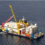
The Arctic Containment System (ACS), was designed by Superior Energy Services-Marine Technical Services, (SES-MTS) to contain and recover uncontrolled oil and gas subsea well leaks by utilizing a barge carrying oil and gas recovery processing equipment.
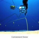
The Containment System starts with a sophisticated and uniquely designed, proprietary containment dome operating as a three phase separator that captures and directs the well leak fluids through separate oil and gas recovery hoses to the processing module equipment that are stationed on the barge.
Containment Dome
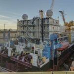
Recovered well leak fluids enter the process module equipment, which consists of a series of two (2) three phase separator vessels and one (1) two phase separator, process heaters and exchangers, pumps, and instrumentation and control systems to separate the oil, gas and water.
Process Module
The recovered oil is either offloaded for recovery or sent to a flare system for burning. The recovered gas is burned in the flare system. Recovered sea water is purified and returned to the sea.
Another way the well leak flows can enter the processing module equipment on the barge is through a capping stack
operation, where a well intervention team directs the well leak fluids through well intervention hoses to a choke manifold on the barge. The choke manifold is piped to the processing module equipment in the same way as the subsea recovery dome oil hose.
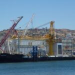
| Source Control Vessel | ||||
| Hull: | Year: 1976 classed with Ice Strengthening | |||
| Class: | Class: A1 Floating Offshore Installation (FOI), Chukchi and Beaufort Seas Coastwise, Restricted Service, RFL5 | |||
| Dimensions: | 316.5′ x 105.75′ w/ approx. 10′ main deck freeboard | |||
| Cranes: | Port side: Sparrows EC1000 (160,600lb capacity) Starboard: Sparrows EC65 (22,000lb capacity) |
|||
| Accommodations: | 72 berths, medical clinic, galley, offices, laundry, lounge | |||
| Comms: | Dual gyro-stabilized satellite data & voice for arctic use | |||
| Service Vessels: | Two 38′ “Bear Cubs” for operations and rescue service maintained on lifts in stern notches | |||
| ROV: | SMD Quantum work class ROV system | |||
| Mooring System (Package) | ||||
| This mooring winch package consist of: | One electric 100 tonne double drum winch with combined mooring / emergency storm anchor drum with auto spooling Three (3) electric 100 tonne double drum mooring winches with auto spooling. Four (4) deck mounted local control stands c/w tarpaulins One (1) central control panel and display Four (4) variable frequency drive cabinets c/w resister banks One (1) PLC cabinet with transport top frame c/w rigging. Eight (8) fixed upper turn down sheaves c/w gypsy wheel chain winch for lift / lowering sliding swivel fairleads Eight (8) sliding swivel fairleads, with mechanical locking in lower operational position Four (4) winch integrated double electro‐hydraulic power units for winch failsafe brake, dog drive clutches, positioning of travelling swivel fairleads and locking in upper storage positions Eight (8) chafe chain 58mm grade U2 x 5.1m long |
|||
| Each winch drum has a capacity of 1200 feet of 2 inch wire, 100 tonne pull and 180 tonne brake hold on the 1st layer. The mooring / storm anchor has a braking capability of 150 tonnes on the 6th wire layer | ||||
| The winch has a 440V / 3 Ph / 60 Hz electric motor prime mover driven by a variable speed drive system | ||||
| Each double drum winch has a local control console and there is a remote control console for all eight winches. Control units have electronic readout of line tension and speed of all anchor handling mooring winches, as well as various other health monitoring parameters | ||||
| Each drum has been supplied with a fixed overboard sheave and a swiveling fairlead which can be raised from its operational position below the water level to allow the anchor to be brought clear of the water during transit | ||||
| Containment Dome | ||||
| Containment Capacity: | 25,000 bpd of light crude oil | |||
| Dimensions: | 15′ x 15′ at base, 20′ x 20′ at top | |||
| Subsea Pumps: | 2x Bornemann SOGS6 each designed for 36kbpd mixture of oil, water, and gas at 65psig | |||
| Buoyancy: | via introduction of Nitrogen | |||
| Positioning: | 8 dome-mounted winches to pre-set anchors | |||
| High-Pressure Choke Manifold | ||||
| Overview: | The high-pressure choke manifold provides well intervention capability via a capping stack. The choke manifold can control the flow of hydrocarbons directly from the well to the process for flaring. Primarily designed for 10,000psi capability. | |||
| Processing | ||||
| Overview: | The 3 phase process separates water from gas and oil. Glycol process heaters provide heat to the process and a chemical injection system introduces anti-foam and demulsifying agents to the system. | |||
| Flare Boom | ||||
| Flaring Capacity: | 25,000 bpd of light crude oil | |||
| Flaring Time: | continuous 45 days expected maximum | |||
| Water Curtain: | 6,000 gpm water curtain to provide areas of safe thermal radiation levels | |||
| Testing | ||||
| Overview: | The system is the only existing “offset” deployment source control method, enabling vessel separation from source for shelf response. This equipment has been successfully proven in regulator attended exercises in 2013, 2014 & 2015. Water Run Test performed in 2014 successfully confirmed intake from Containment Dome pumps through the process facilities. Commissioning finalized in 2015 enabling the first US offshore Arctic drilling program. | |||
Our inventory changes weekly. If you don’t see what you’re looking for please give us a call at +1 (225) 301-2873 or email us to discuss what you’re looking for.